Appendix B: F75111N DIO & Watchdog Device
The Arrakis Pico MK4 includes optional DIO Ports. This Appendix provides an introduction to programming these ports.
Watchdog Timer under DOS
The necessary software resources for programming the watchdog timer can be accessed from the Driver Download section:
Source file: F75111_Dos_Src.rar
Binary file: F75111_Dos_Bin.rar
USERNAME & PASSWORD: sf
How to Use the Demo Application:
Boot into the MS-DOS Operating System.
Execute the
75WDT.EXEbinary file.Input
1to enable the WDT timer or0to disable it.Input the number of seconds for the chip countdown and reset the computer.
Introduction:
How to use the Watchdog Timer Demo in different ways:
WriteI2CByte(I2CADDR, CONFIG, 0x03); // Set Watchdog Timer function
WriteI2CByte(I2CADDR, WDT_TIMER, timer); // Set Watchdog Timer range from 0-255
WriteI2CByte(I2CADDR, WDT_TIMER_CTL, 0x73); // Enable Watchdog Timer in second and pulse mode
Or:
WriteI2CByte(I2CADDR, WDT_TIMER_CTL, 0x00);
Or:
void pause(int time) {
    asm mov ah,0h; // Ah = 00 Read System Time Counter
    asm int 1ah;   // Read time from Time Counter and store it in DX register
    asm add dx, time;
    asm mov bx, dx;
label:
    asm int 1ah;
    asm cmp bx, dx;
    asm jne label;
}
Watchdog Timer and DIO under Windows:
The necessary software resources for programming the watchdog timer can be accessed from the Driver Download section:
Source file: F75111_DIOSrc.rar
Binary file: F75111_DemoBin.rar
USERNAME & PASSWORD: sf
How to Use the Demo Application:
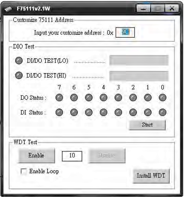
Press the
Startbutton to test the DIO function.Press the
Enablebutton to test the WDT function.Press the
Disablebutton to disable the WDT.Check the
Enable Loopbox and pressEnableto do a WDT loop test.Press
Install WDTto set the system to autorun this application when booting. Press it again to remove the application from booting. The icon will show when active.
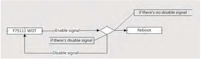
The F75111 will send F75111_SetWDTEnable(BYTE byteTimer) including a timer parameter. If there’s no disable signal (F75111_SetWDTDisable()) to stop it before the timer countdown reaches 0, the system will reboot. If a disable signal is received, it will reset the Enable WDT signal to prevent a reboot loop.
Introduction:
Initial Internal F75111 port address (0x9c) Define GPIO1X, GPIO2X, GPIO3X as input or output and enable the WDT function pin.
Set F75111 DI/DO (Sample Code Below to Get Input Value/Set Output Value):
DO:
InterDigitalOutput(BYTE byteValue)DI:
InterDigitalInput()
Enable/Disable WDT:
Enable:
F75111_SetWDTEnable(BYTE byteTimer)Disable:
F75111_SetWDTDisable()
Pulse Mode:
Example to set GP33, 32, 31, 30 output to 1mS low pulse signal:
{
    this->Write_Byte(F75111_INTERNAL_ADDR, GPIO3X_PULSE_CONTROL, 0x00); // Set low pulse output
    this->Write_Byte(F75111_INTERNAL_ADDR, GPIO3X_PULSE_WIDTH_CONTROL, 0x01); // Set pulse width to 1mS
    this->Write_Byte(F75111_INTERNAL_ADDR, GPIO3X_CONTROL_MODE, 0x0F); // Set GP33, 32, 31, 30 to output function
    this->Write_Byte(F75111_INTERNAL_ADDR, GPIO3X_Output_Data, 0x0F); // Set GP33, 32, 31, 30 output data
}
Initialize Internal F75111:
void F75111::InitInternalF75111() {
    this->Write_Byte(F75111_INTERNAL_ADDR, GPIO1X_CONTROL_MODE, 0x00); // Set GPIO1X to input function
    this->Write_Byte(F75111_INTERNAL_ADDR, GPIO3X_CONTROL_MODE, 0x00); // Set GPIO3X to input function
    this->Write_Byte(F75111_INTERNAL_ADDR, GPIO2X_CONTROL_MODE, 0xFF); // Set GPIO2X to output function
    this->Write_Byte(F75111_INTERNAL_ADDR, F75111_CONFIGURATION, 0x03); // Enable WDT OUT function
}
Set Output Value:
void F75111::InterDigitalOutput(BYTE byteValue) {
    BYTE byteData = 0;
    byteData = (byteData & 0x01) ? byteValue + 0x01 : byteValue;
    byteData = (byteData & 0x02) ? byteValue + 0x02 : byteValue;
    byteData = (byteData & 0x04) ? byteValue + 0x04 : byteValue;
    byteData = (byteData & 0x80) ? byteValue + 0x08 : byteValue;
    byteData = (byteData & 0x40) ? byteValue + 0x10 : byteValue;
    byteData = (byteData & 0x20) ? byteValue + 0x20 : byteValue;
    byteData = (byteData & 0x10) ? byteValue + 0x40 : byteValue;
    byteData = (byteData & 0x08) ? byteValue + 0x80 : byteValue; // Get value bit by bit
    this->Write_Byte(F75111_INTERNAL_ADDR, GPIO2X_OUTPUT_DATA, byteData); // Write byteData value via GPIO2X output pin
}
Get Input Value:
BYTE F75111::InterDigitalInput() {
    BYTE byteGPIO1X = 0;
    BYTE byteGPIO3X = 0;
    BYTE byteData = 0;
    this->Read_Byte(F75111_INTERNAL_ADDR, GPIO1X_INPUT_DATA, &byteGPIO1X); // Get value from GPIO1X
    this->Read_Byte(F75111_INTERNAL_ADDR, GPIO3X_INPUT_DATA, &byteGPIO3X); // Get value from GPIO3X
    byteGPIO1X = byteGPIO1X & 0xF0; // Mask unuseful value
    byteGPIO3X = byteGPIO3X & 0x0F; // Mask unuseful value
    byteData = (byteGPIO1X & 0x10) ? byteData + 0x01 : byteData;
    byteData = (byteGPIO1X & 0x80) ? byteData + 0x02 : byteData;
    byteData = (byteGPIO1X & 0x40) ? byteData + 0x04 : byteData;
    byteData = (byteGPIO3X & 0x01) ? byteData + 0x08 : byteData;
    byteData = (byteGPIO3X & 0x02) ? byteData + 0x10 : byteData;
    byteData = (byteGPIO3X & 0x04) ? byteData + 0x20 : byteData;
    byteData = (byteGPIO3X & 0x08) ? byteData + 0x40 : byteData;
    byteData = (byteGPIO1X & 0x20) ? byteData + 0x80 : byteData; // Get correct DI value from GPIO1X & GPIO3X
    return byteData;
}
Enable Watchdog:
void F75111_SetWDTEnable(BYTE byteTimer) {
    WriteByte(F75111_INTERNAL_ADDR, WDT_TIMER_RANGE, byteTimer); // Set Watchdog range and timer
    WriteByte(F75111_INTERNAL_ADDR, WDT_CONFIGURATION, WDT_TIMEOUT_FLAG | WDT_ENABLE | WDT_PULSE | WDT_PSWIDTH_100MS);
    // Enable Watchdog, Setting Watchdog configure
}
Disable Watchdog:
void F75111_SetWDTDisable() {
    WriteByte(F75111_INTERNAL_ADDR, WDT_CONFIGURATION, 0x00); // Disable Watchdog
}
IO Device: F75111 VB6 under Windows
The necessary software resources for programming the watchdog timer can be accessed from the Driver Download section:
Source file: 75111_VB_v10.rar
Binary file: 75111_VB_Src.rar111_DemoBin.rar
USERNAME & PASSWORD: sf
How to Use the Demo Application
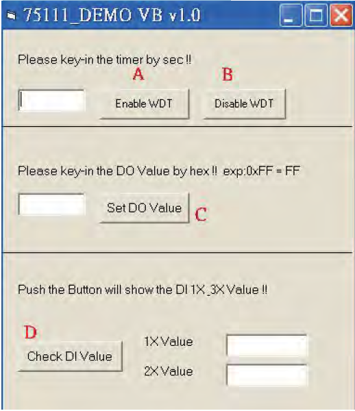
A Function - Enable WDT timer: Enter the value in seconds, then the system will reboot after the specified time.
B Function - Disable WDT timer: Press the button to clear the WDT timer value.
C Function - Set DO Value: Enter the DO value in hex, then press the button.
D Function - Check DI Value: The two text boxes on the right display DI 1X & 2X values when you press the button.
SDK Function Introduction
Function EnableWDT:
Function EnableWDT(timer As Integer)
    Call WriteI2CByte(&H3, &H3)
    Call WriteI2CByte(&H37, timer)
    Call WriteI2CByte(&H36, &H73)
End Function
Function DisableWDT:
Function DisableWDT()
    Call WriteI2CByte(&H36, &H0)
End Function
Function SetDOValue:
Function SetDOValue(dovalue As Integer)
    Call WriteI2CByte(&H23, &H0)
    Call WriteI2CByte(&H20, &HFF)
    Call WriteI2CByte(&H2B, &HFF)
    Call WriteI2CByte(&H21, dovalue)
End Function
Function CheckDIValue:
Function CheckDIValue()
    Dim GPIO1X As Integer
    Dim GPIO3X As Integer
    Dim DI1Xhex As String
    Dim DI3Xhex As String

    Call ReadI2CByte(&H12, GPIO1X)
    Call ReadI2CByte(&H42, GPIO3X)

    DI1Xhex = Hex(GPIO1X)
    DI3Xhex = Hex(GPIO3X)

    Text3.Text = "0x" + DI1Xhex
    Text4.Text = "0x" + DI3Xhex
End Function
Watchdog Timer and DIO under Linux
The necessary software resources for programming the watchdog timer can be accessed from the Driver Download section:
Source file: F75111v2.0L.tar.gz
Binary file: F75111v2.0LBin.tar.gz
USERNAME & PASSWORD: sf
How to Compile the Source Code
Compile with Code::Blocks:
Download and install Code::Blocks with the command
apt-get install codeblocks.Open the existing project (F75111.cbp) in Code::Blocks and click the compile button.
Add the option
pkg-config --libs gtk+-2.0 gthread-2.0in “Project -> Build Option -> Linker Setting -> Other linker option”.
Compile with “make”:
Navigate to the F75111 directory:
cd F75111.Compile the source:
make.Execute the binary file:
src/f75111.
How to Use the Demo Application
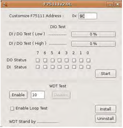
Press the “Start” button to test the DIO function.
Press the “Enable” button to test the WDT function.
Press the “Disable” button to disable the WDT.
Check the “Enable Loop” box and press “Enable” to do a WDT loop test.
Press “Install” to set the system to autorun this application at boot, press “Uninstall” to remove it from boot.
If WDT is enabled, the system icon will blink.
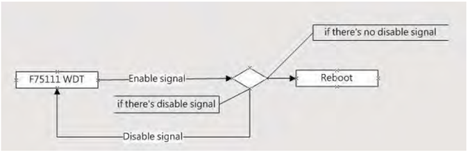
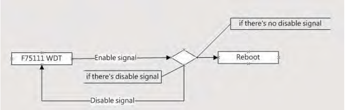
The F75111 will send F75111_SetWDTEnable(BYTE byteTimer) with a parameter timer. If no disable signal (F75111_SetWDTDisable()) is received before the timer counts down to 0, the system will reboot. If a disable signal is received, it will resend the enable WDT signal to prevent a reboot loop.
Introduction
IO Function in the file SMBus.c:
void SMBusIoWrite(BYTE byteOffset, BYTE byteData) {
    outb(byteData, m_SMBusMapIoAddr + byteOffset);
}

BYTE SMBusIoRead(BYTE byteOffset) {
    DWORD dwAddrVal;
    dwAddrVal = inb(m_SMBusMapIoAddr + byteOffset);
    return (BYTE)(dwAddrVal & 0x0FF);
}
Init Internal F75111:
void F75111::InitInternalF75111() {
    this->Write_Byte(F75111_INTERNAL_ADDR, GPIO1X_CONTROL_MODE, 0x00); // Set GPIO1X to Input function
    this->Write_Byte(F75111_INTERNAL_ADDR, GPIO3X_CONTROL_MODE, 0x00); // Set GPIO3X to Input function
    this->Write_Byte(F75111_INTERNAL_ADDR, GPIO2X_CONTROL_MODE, 0xFF); // Set GPIO2X to Output function
    this->Write_Byte(F75111_INTERNAL_ADDR, F75111_CONFIGURATION, 0x03); // Enable WDT OUT function
}
Set Output Value:
void F75111::InterDigitalOutput(BYTE byteValue) {
    BYTE byteData = 0;
    byteData = (byteData & 0x01) ? byteValue + 0x01 : byteValue;
    byteData = (byteData & 0x02) ? byteValue + 0x02 : byteValue;
    byteData = (byteData & 0x04) ? byteValue + 0x04 : byteValue;
    byteData = (byteData & 0x80) ? byteValue + 0x08 : byteValue;
    byteData = (byteData & 0x40) ? byteValue + 0x10 : byteValue;
    byteData = (byteData & 0x20) ? byteValue + 0x20 : byteValue;
    byteData = (byteData & 0x10) ? byteValue + 0x40 : byteValue;
    byteData = (byteData & 0x08) ? byteValue + 0x80 : byteValue; // Get value bit by bit
    this->Write_Byte(F75111_INTERNAL_ADDR, GPIO2X_OUTPUT_DATA, byteData); // Write byteData value via GPIO2X output pin
}
Get Input Value:
BYTE F75111::InterDigitalInput() {
    BYTE byteGPIO1X = 0;
    BYTE byteGPIO3X = 0;
    BYTE byteData = 0;
    this->Read_Byte(F75111_INTERNAL_ADDR, GPIO1X_INPUT_DATA, &byteGPIO1X); // Get value from GPIO1X
    this->Read_Byte(F75111_INTERNAL_ADDR, GPIO3X_INPUT_DATA, &byteGPIO3X); // Get value from GPIO3X
    byteGPIO1X = byteGPIO1X & 0xF0; // Mask unnecessary value
    byteGPIO3X = byteGPIO3X & 0x0F; // Mask unnecessary value
    byteData = (byteGPIO1X & 0x10) ? byteData + 0x01 : byteData;
    byteData = (byteGPIO1X & 0x80) ? byteData + 0x02 : byteData;
    byteData = (byteGPIO1X & 0x40) ? byteData + 0x04 : byteData;
    byteData = (byteGPIO3X & 0x01) ? byteData + 0x08 : byteData;
    byteData = (byteGPIO3X & 0x02) ? byteData + 0x10 : byteData;
    byteData = (byteGPIO3X & 0x04) ? byteData + 0x20 : byteData;
    byteData = (byteGPIO3X & 0x08) ? byteData + 0x40 : byteData;
    byteData = (byteGPIO1X & 0x20) ? byteData + 0x80 : byteData; // Get correct DI value from GPIO1X & GPIO3X
    return byteData;
}
Enable WatchDog:
void F75111_SetWDTEnable(BYTE byteTimer) {
    WriteByte(F75111_INTERNAL_ADDR, WDT_TIMER_RANGE, byteTimer); // Set WatchDog range and timer
    WriteByte(F75111_INTERNAL_ADDR, WDT_CONFIGURATION, WDT_TIMEOUT_FLAG | WDT_ENABLE | WDT_PULSE | WDT_PSWIDTH_100MS);
    // Enable WatchDog, Setting WatchDog configuration
}
Disable WatchDog:
void F75111_SetWDTDisable() {
    WriteByte(F75111_INTERNAL_ADDR, WDT_CONFIGURATION, 0x00); // Disable WatchDog
}