I/O Ports
Connector Guide
This section provides a detailed overview of all connectors, switches, and indicators needed for peripheral setup. Before installation, ensure that the system is powered off and disconnected from any power sources.
Switches and Jumpers
JSB1: CMOS Data Clear
1-2: Normal set
2-3: CMOS data clear
Quick List of Connectors
CBT1: CMOS Battery in a 1x2 pin (1.25mm) wafer.
CU1, CU2, CU3: USB3.1 type A connectors.
CU9: USB2.0 type A connector.
CU6, CU7, CU8: USB 2.0 ports, each with a 1x4 pin (1.25mm) wafer.
CL1, CL2, CL3: RJ45 LAN connectors for network connections.
TB1: Power button / DC-IN with a TB 5-pin (3.5mm) connector.
TB2: TB 8-pin (3.5mm) connector.
CFP1: Front Panel connector with a 2x5 pin (2.0mm) wafer.
CO1: SMBus connection via a 1x4 pin (1.25mm) wafer.
SIM1: Nano SIM card socket for mobile connectivity.
NGFF1: M.2 B key socket for 2242/2280 form factors with H=8.5, featuring 75 pins.
NGFF2: M.2 B key socket for 2242/3042 form factors with H=8.5, featuring 75 pins.
HDMI1: HDMI type A video output connector for displays.
Safety and Handling
Safety: Always ensure the system is completely powered off and disconnected from any power source before connecting or disconnecting peripherals.
Handling: Carefully handle connectors and avoid forceful insertion to prevent damage to pins and ports.
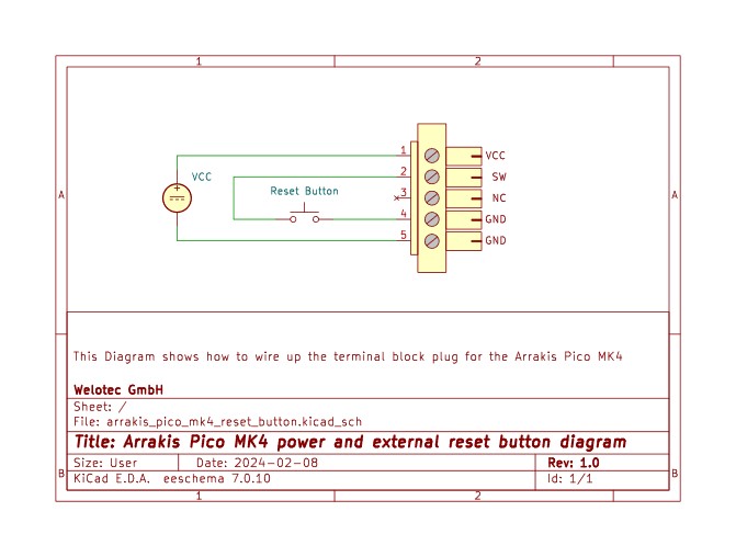
Power Connector Pin-Out
Attention: Do not connect Voltage to the SW Pin on the Power Connector!
Power Connector Pin-Out |
|
|---|---|
Vcc |
12-24V |
SW |
External Power Switch Connector |
NC |
Not Connected |
GND |
Ground |
GND |
Ground |
Power Connector wiring schematic
COM and DI/DO Connector
COM1 RS232 or RS485 form BIOS select , default set RS232
TB2-TB 8pin connector (3.5mm)(RS232 Mode)
PIN NO. |
DESCRIPTION |
PIN NO. |
DESCRIPTION |
|---|---|---|---|
1 |
NTXD |
5 |
|
2 |
NC |
6 |
|
3 |
NRXD |
7 |
|
4 |
GND |
8 |
TB2-TB 8pin connector (3.5mm)(R485 Mode)
PIN NO. |
DESCRIPTION |
PIN NO. |
DESCRIPTION |
|---|---|---|---|
1 |
NC |
5 |
|
2 |
RS485_DATA- |
6 |
|
3 |
RS485_DATA+ |
7 |
|
4 |
GND |
8 |
2-4 Digital Input / Output / Watch Dog Time
2-4-1 TB2-TB 8pin connector (3.5mm)
Note:
F75111N-1 I2C bus address 0x9C.
DI input range is +12V or +24V.
DI pin default pull up 10KΩ to +3.3V.
DO output voltage rail from DC-in(+12V or +24V) and current limit max 2A.
For F75111N I2C watch dog timer device:
Input low Voltage (VIL):+0.8 Max,
Input High Voltage (VIH): +2V Min
Output low Current (IOL):10mA (Min) VOL=0.4V
Output High Current (IOH):-10mA (Min) VOL=2.4V
Watch Dog Time value 0~255 sec
The system will be issued reset. When WDT is enable the hardware start down counter to zero. The reset timer has 10~20% tolerance upon the Temperature.
Antennae Connector Position LTE/5G:
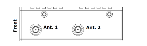
Antennae Connector Position Wi-Fi:
Ant. 1: WiFi 1 Ant. 2: WiFI 2 The WiFi Connectors are equivalent.
Connector Type: SMA-RP